 |
||||
|
|
|
|||
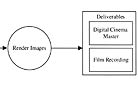
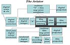
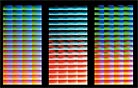
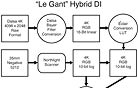
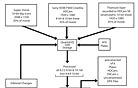
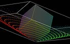
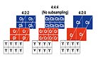
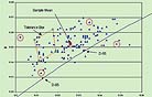
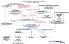
Pacific Title & Art Studio eventually opted for the TIFF format when formulating a DI workflow for the StEM digital projection test film. StEM (AC Jan. ’04) was conceived by the ASC and the DCI studio coalition as high-quality evaluation imagery that was offered to digital cinema product developers of servers, digital projectors, etc. (see diagram) Pacific Title scanned the footage at 6K resolution in 16-bit DPX resolution on a Northlight scanner — 164MB per frame. When the data was stuffed into a 16-bit DPX container, the facility ran into problems because few software implementations correctly supported the format’s full specifications. “After casting about for a solution,” recalls Denis Leconte, head of software development at Pacific Title, “we settled on 16-bit TIFF as a reasonably well-supported data exchange standard. This was first intended to be converted prior to Lustre-ready delivery. But as we found more software having trouble with 16-bit DPXs, we moved the TIFF conversion higher into the pipeline, to the point where it ended up being done during the first resize from 6K to 4K straight off the scanner. “One important note regarding the use of TIFF,” he continues, “is that the file format was used as a container for printing density values that were stored as 16-bit printing density values over a 2.048 density range [the range of values that the format can store]. The TIFF spec does not allow for this type of data format per se, so the photometric interpretation tag was left as RGB color and further processing was done with the assumption that pixel data represented printing density.” Thus, one of the problems of file formats arises: you can use any format to store the bits, but unless you know exactly what the original data represents, your image may not look the way it was intended. Adds Pacific Title producer Jim Houston, “The Academy’s Science and Technology Council is taking on pilot projects to work on some industry-wide problems. One of them is working on this file format issue to come up with a simplified format for a digital source master that will satisfy the user requirements for higher bit depth, higher resolution files. We’re just at the beginning stages. If we can have a digital file format that is as widespread and compatible as 35mm negative, digital workflow will be greatly improved.” If the StEM footage were taken to a different post facility, the general workflow steps — scanning and converting to a file format, dust-busting and sharpening, color grading, and digital cinema master creation, and possibly a DI filmout — would be the same, as would many of the tools, but the processing and transport would be different. Each facility designs (or cobbles together) a system to accomplish its goals. However, just because a “Lustre” logo is on the box doesn’t mean that two high-end DI facilities’ Discreet Lustres will function the same, just like a 1979 Camaro Z28 with a blower, ported and polished heads and straight pipes won't perform the same as a showroom-stock ’79 Z28. DI facilities hot-rod their gear, optimizing the performance to fit within their custom workflows. EFilm senior colorist Steve Scott and Roger Deakins ASC, BSC graded The Village (AC Aug. ’04) on a proprietary system that has its foundation in Colorfront technology (see diagram). It is updated continually with EFilm’s own modifications. (More likely than not, all facilities have juiced every piece of gear, from scanners to color correctors to recorders, at least a little to get their respective pipelines flowing the way they prefer.) The Colonel has his recipe, Coca-Cola has its formula, and DI facilities have their “secret sauce,” which undoubtedly includes proprietary Look-Up Tables (LUTs). Most projects that are shepherded through a DI strive to maintain the CMY filmic look and quality, but you don’t see that naturally on an RGB color space display. That doesn’t work when the cinematographer and colorist are grading a motion picture on a monitor and digital projector and the motion picture will be shown on film print stock in theaters across the globe. This is where LUTs come in. A LUT is a facility’s tool to shift from one color space to another — to get a scan to display correctly on the monitor requires a certain LUT, and to display on a digital projector requires a different LUT. LUTs shift an input value to a particular output value; for example, they shift a specific color of yellow to a deeper shade to emulate how the yellow would be created on Kodak Vision print stock. There are limits to this shifting, however. For a more numerical example, a 10-bit log file has assigned values from 0-1023 (210-1=1023) that correspond to densities on the negative. If a LUT is written to emulate the look of a +1 stop increase (which would equal approximately +90 code values), 0 becomes 90, 1 becomes 91 and so on. However, 934 + 90 = 1023, not 1024. 935 + 90 = 1023, not 1025, etc. 1023 is the limit, and all numbers beyond that are clipped back to 1023 because they fall out of the gamut of reproducible colors. That means it is an artifact, but one that may not be perceivable. “If you look at RGB space as a cube,” says Joshua Pines, vice president of imaging research and development at Technicolor Digital Intermediates (TDI), “you actually can warp it, which is what happens to the densities as they go from a negative to a print. Some of it may fall out of gamut. It depends on what the gamut is that you are producing. What we’re doing at TDI is taking spectral radiometer readings in XYZ [color space] of the film projection of each of the lattice points, and then figuring out what digital values we must send out to the digital projector to produce those same XYZs.” A lattice, or table, is a more manageable grid of points from which to measure (see diagram). “You don’t construct a table that has every single value — it will be such an enormous table!” Pines exclaims. “But you can do a bunch of points and interpolate between them. Let’s say that instead of doing 1,000 reds, 1,000 green and 1,000 blues, we do 20 reds by 20 greens by 20 blues, or perhaps 16x16x16, 25x25x25, 65x65x65, etc. The points are equally spaced from white to black, and it’s a more reasonable table to measure. We have our input coming in, and if we are lucky enough to hit on one of those points, we already will know what the output will be for digital emulation of that film print. More often than not, we will not hit one of those points. We will be in between in RGB space, the middle of the cube. That means we will have to take an average of the known values depending on where we will have to interpolate between the known values at the corners of the cube, and that is how a 3-D LUT works. I prefer to call them ‘interpolated lattice deformations’ because the lattice is deformed when we interpolate between actual lattice points.” So, LUTs can emulate the characteristics of actual negative and print film stocks. Kodak and Fuji have their own LUTs for their stocks. Kodak LUTs are available with the Kodak Display Manager and Look Management System products. Fuji’s LUTs for its negative and print stocks are available by request. A DI lab like TDI may also craft its own custom LUT by analyzing and measuring the film stock, writing the LUT code and then perfecting it through trial and error. LUTs also can shift colors and create unique looks, as well as transform color spaces. The LUTs’ key role in the DI workflow has led several companies, such as Filmlight (Truelight), Kodak (TCS), Thomson (Luther), Imagica (Galette) and others, to introduce color-space converter boxes that come with LUTs designed by the manufacturers. Many facilities also download their custom LUTs into these boxes. Scanner manufacturers, such as Arri with its Arrilaser and Celco with its Fury, have gotten into the color mix as well with onboard color-management systems that don’t require LUTs to be plugged in — they operate with preset color profiles. There is a simple LUT, a 1-D LUT, that you may not realize is at work during basic color correction. If you tell your colorist to make a scene cooler and he then adds a little blue, a 1-D LUT for the blue channel has just been applied to the digital file for display. Notes Pines, “An LUT is a table of numbers — a single number goes in, another comes out. Blue goes in, blue comes out, and so on. Something you can never do with a 1D LUT is saturation, taking color and turning it into grayscale values, because the final red output, for example, doesn’t just depend on the red, but also the green and the blue input values.” For the DLP digital projector used in color grading, Pines wrote the Technicolor two-strip- and three-strip-emulating LUTs for The Aviator (AC Jan. ’05), shot by Robert Richardson, ASC, based on emulated looks visual-effects supervisor Rob Legato had produced in Adobe After Effects and Photoshop (see image a, image b, image c and image d). “Marty Scorsese has a collection of old two-strip films,” says Pines. “We took a whole reel of a print, scanned it, put it through our calibrated digital projector and tweaked it side by side with the film projector so that they looked identical. Therefore, we had a digital footprint of what the two-strip film-print color gamut was. We did the same thing with three-strip with frames from Robin Hood. We got that information not only for visual reference, but also to map the color canvas [with tables]. We characterized those, turning them into 3-D LUTs.” A 3-D LUT has three input channels and three output channels. The red, for example, could be dependent on all three channels of input. The same goes for blue and green. “In practice, a full-blown 3-D LUT would be way too big for current computers and electronics,” Pines indicates.. “Instead, we use a ‘sparse 3-D LUT’ and interpolate between the lattice points.” (see diagram) |
|
|||
|
<< previous || next >> |
||||
|
|
|
|
|
|

|
|
|
|
|
|
 |
|
|
|
 |
|
|
|
||
|
|
 |
|
|
|
||
|
|
 |
|
|
|
||
|
|
 |
|
|
|
||
|
|
 |
|
|
|
||
|
|
 |
|
|
|
||
|
|
 |
|
|
|
||
|
|
 |
|
|
|
||
|
|
 |
|
|
|
||
|
|
 |
|
|
|
||
|
|
 |
|
|
|
||
|
|
 |
|
|
|
||
|
|
 |
|
|
|
||
|
|
 |
|
|
|
||